Preliminary report on the St Savvas anchor, which failed with lethal consequences on 27th March 2026
I would like to extend my condolences to all those who were touched by this terrible event. It is my earnest intent, through the pages of Crag Chemistry, to shine a light on such wild and unexpected failures as come at us out of left-field. I am certain that we can learn how to tame them.
Introduction:
It is not my intention to detail the events of the fatal accident, or to get drawn into what we, as a community, should or should not be doing in response to such events.
I have months of work ahead of me investigating various aspects of how such an anchor came to fail. At this stage I have not looked beyond the two anchor bolts themselves. However, I have discovered enough to state that this is a very unusual mode of failure – it is certainly the first time I have encountered it.
Further to this, I now know enough to state that there are other dangerous bolts of this type out there waiting to trap the unwary and thus wish this short report to serve as a warning.
Key Findings:
This is what I know with reasonable surety. Each point will be elaborated further down the page. The anchor was comprised of two bolts, and thus, where necessary, I’ll differentiate between them as lefthand (LH) and righthand (RH).
- Bolt type: Wedge style expansion bolt 10mm x 60mm.
- Material: Stainless steel 316L.
- Percentage Austenite: close to 100%.
- Brand: Petzl Goujon.
- Age: approx. 24 years.
- Failure Point: roughly transverse, some millimetres below the rock surface.
- Failure Type: stress cracking –
- not Cl mediated stress corrosion cracking (Cl-SCC): there is no evidence.
- not SRB mediated sulphide stress cracking (SRB-SSC): there is no evidence.
- but likely prime cause is hydrogen assisted cracking (HAC): extreme cold-working of the rolled threads has caused a transition from chloride SCC to hydrogen‑assisted SCC.
Details:
1. Bolt Type:
Note: the damage to the surface is a consequence of extracting them from the rock.
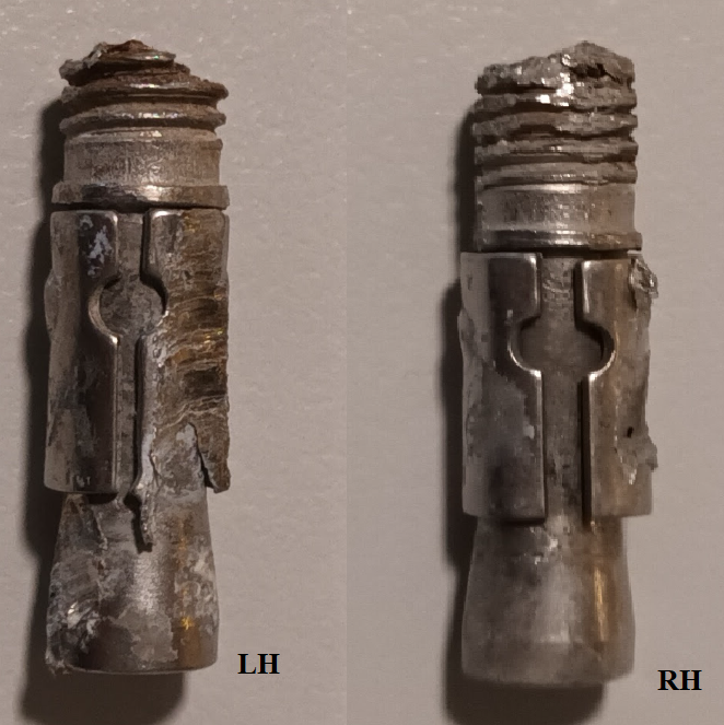
Note the absence of corrosion products, even after 24 years in the field.
2. Material:
We have had samples of both bolts analysed by optical emission spectroscopy (OES). The major components fell within the 316L specification, and we were able to eliminate the possibility of embrittlement by the likes of sulphur and phosphorus.
| LH (S-JP8) | RH (S-JP9) | |
| Cr | 16.9 | 16.8 |
| Ni | 10.1 | 10.3 |
| Mo | 2.0 | 2.02 |
| C | 0.02 | 0.02 |
| S | <0.001 | <0.001 |
| P | 0.011 | 0.011 |
You can view the lab report here.
3. Percentage Austenite:
Magnetic susceptibility was estimated by a micro-balance technique. These values were then converted to % austenite using a calibration curve derived from XRD measurements. Many thanks to Luigi Pisani for the XRD work.
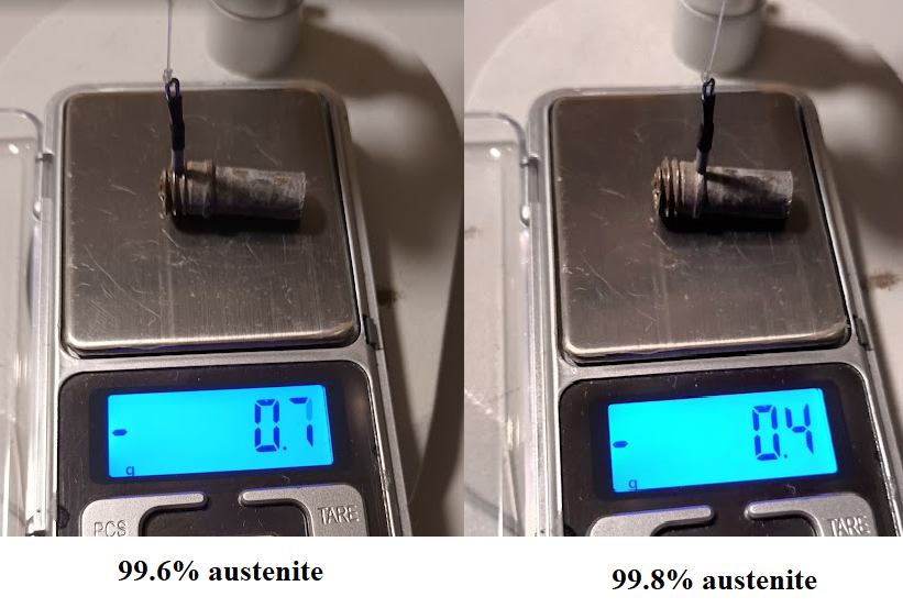
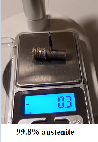
It is a property of 316 to maintain its austenitic state during cold-working. However, considering the degree of cold-working revealed by the micrograph down page, and considering the nickel content is just on the 10% threshold, it is surprising that there has been so little conversion from austenite to martensite during processing of these parts.
4. Brand:
All the bolts on St Savvas appear to be the same make, and the nuts, where we have them, are stamped Petzl Goujon. I don’t have nuts for the failed anchor bolts, but the body of the bolt matches others I have.
This what they look like. Note that this an example from elsewhere in Kalymnos
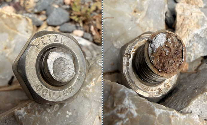
This bolt would have been put on the market sometime in early 2000. However, attempts to match it to Petzl literature have been confusing. We have not been successful in locating a manufacturer’s specification for it.
5. Age:
We have adequate records to assert the bolts were placed in 2002, and thus the age must be approx. 24 years.
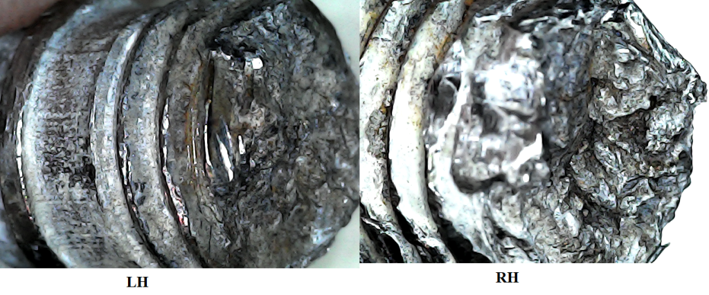
6. Failure Point:
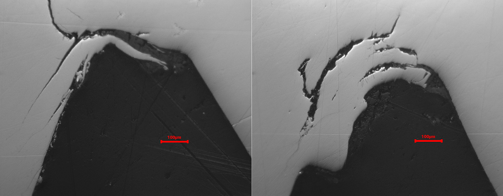
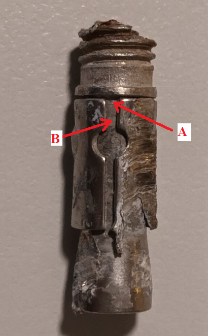
The lefthand anchor, post failure, is pictured below. The righthand anchor presented in a similar fashion. This manner of snapping just below the surface is similar to that we see with the majority of SRB mediated fractures where we know anoxic conditions are a strict requirement.
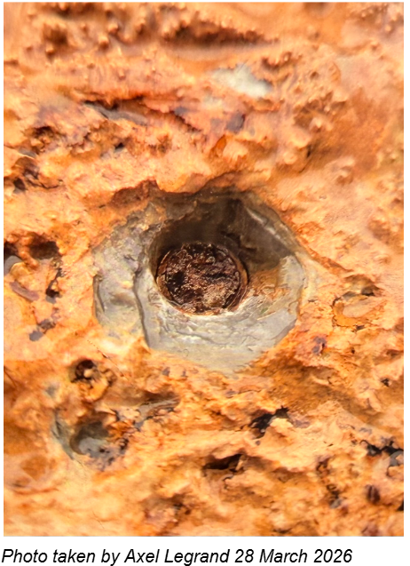
Of course, this need not be SRB attack, and, whatever the mechanism is, the preference for anoxic conditions is worth noting.
7. Failure Type:
We are certainly looking at a progressive cracking phenomenon that is being driven by the stress field of the preload applied during installation. However, for the austenitic stainless steels, there are a number of quite different possible causes for such a thing, and we will consider each of them in turn. Firstly, let’s take a closer look at what is actually present before getting influenced by that we might expect to see.
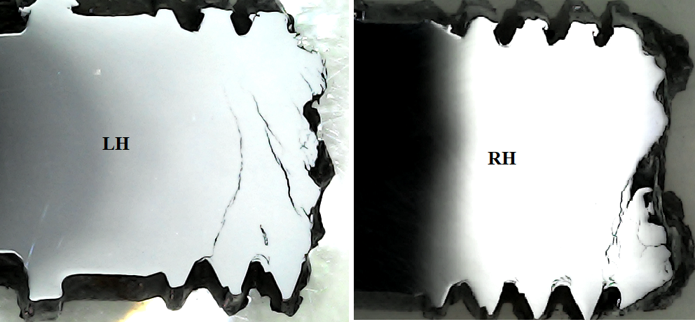
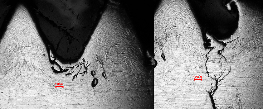
Despite the fact the thread crests are a bit mangled as a result of being grabbed during extraction from the rock, we can see that smaller cracks seem to cluster into major crack systems. On the LH specimen, the crack system originating from a thread root is obvious. Some of the other systems may be originating from the primary failure crack itself. Remember we at looking at a pattern that has had decades to develop.
However, this simple view becomes more complex when we look closer. Note that I say complex and not chaotic because the underlying metallic microstructure seems to be exerting some tendency toward order.
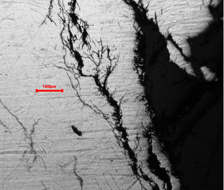
Note the large number of fine secondary cracks and note also that often they are branching from the main cracks with large angular deviation. Their direction is certainly not conformal with the general direction of the stress along the length of the bolt.
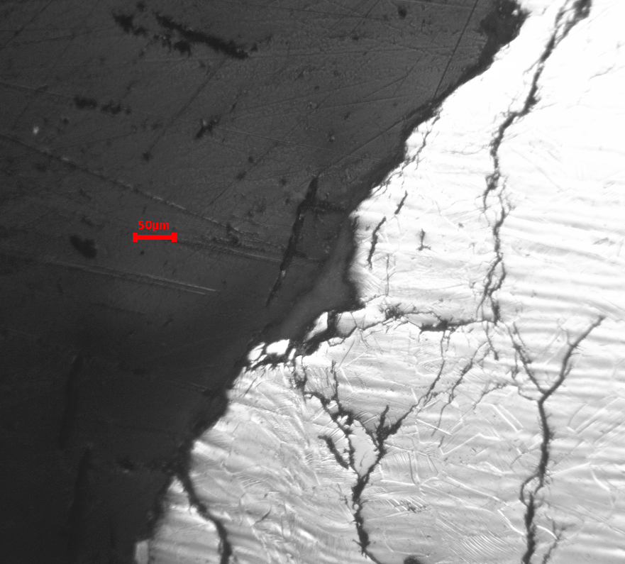
Taking a closer look at the fine cracks, we see straight sections, orientated, not randomly, but in a reduced set of preferred directions. We also see zigzagging where a developing crack has jumped from one preferred orientation to another.
A final point to consider is the question of whether the fracture is running between grains (intergranular) or across them (transgranular). This can point to one mechanism rather than another.
And here we come to another important observation. The metal, even at the centre of the bolt, has been so work-hardened, presumably by the final dimensional reduction of the bar stock, that it is hard to discern actual grains. Numerous mechanical twins confuse the boundaries.
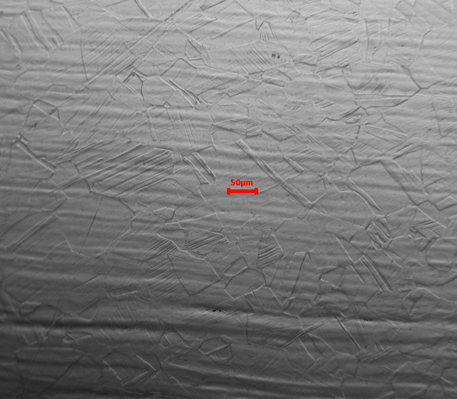
Guessing from the extent of some of the twin structures, it seems the average grain size is of the order of 80um. This is perhaps some five times greater than I would expect for a production bolt given the fact that smaller grain sizes favour higher tensile strengths.
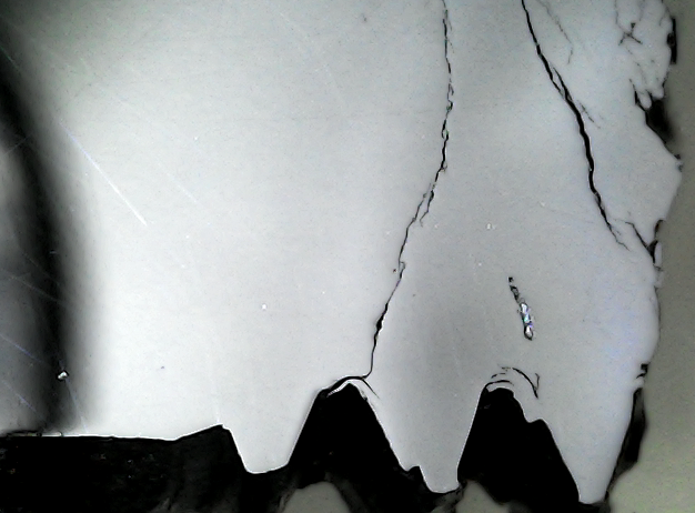
If we look at a fracture edge where the microstructure is obvious. It seems the fracture is transgranular, even though the grain boundaries themselves are not easy to discern.
Let’s now consider some possible mechanisms.
mode 1: Cl-mediated stress corrosion cracking (Cl-SCC):
This is the star demon of the climbing bolt world. Everyone knows about it. Everyone attributes failure to it, and yet I am still looking for a single example that meets my standards of proof.
In the coming months, watch this failure at St Savvas get labelled as a Cl-SCC event. And, just like that, the matter will be all over – “sea cliffs, stainless steel, I told you so … blah blah blah … time to move on”.
Such is the danger of not knowing what you don’t know. As I will reveal, there is a hazardous, bolt-production issue right here, that we risk losing sight of in the rush to apply the Cl-SCC label.
But first, we must give SCC its due. It is most definitely a real phenomenon. It’s not magic. Its key thermodynamics are understood, and it is by working with these, that I can develop an argument that says it is unlikely to manifest on a climbing crag. If you like pain, then I detail the case for Tonsai/Railay here. The case for St Savvas would differ somewhat from this, but rather than sidetrack, I’ll go straight for the evidence.
SCC requires very high chloride levels at the attack site. By very high, consider that sea water is as nothing in the matter, and that saturated sodium chloride also would be hopelessly weak. However, if by some process, we could magic sufficient chloride into the spaces surrounding those anchor bolts, then 24 years later, the evidence of attack would be obvious. The SCC process is initiated by the development of manifold corrosion pits, some of which will develop the correct geometry to raise the stress of the tightened bolt to a level that exceeds the critical stress intensity for the steel. A crack will be initiated.
I don’t need to go on to discuss the mechanism of crack propagation. It is enough to know that a bolt that has failed by SCC, after 24 years, will show three things, a) corrosion products, b) a pitted surface and, c) any cracks under development will arise from a pit on the surface.
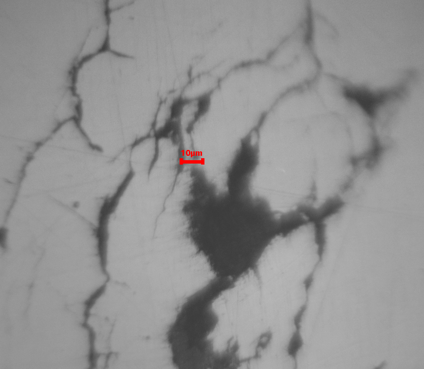
If we look at the photo below, we see stress cracks that have opened without initiation by a corrosion pit. In fact, there are no pits anywhere, and there are no corrosion products.
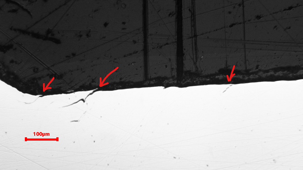
Whatever is initiating this cracking, it is not Cl pitting. This is something else going on. Look at the initiation of the major crack system at the thread root in the picture below.
mode 2: sulphide stress cracking mediated by sulphate reducing bacteria (SRB-SSc):
This is by far the most common agency of the aggressive corrosion of climbing bolts. I contend that most published attributions to Cl-SCC would instead have been assigned to SRB-SSC if checks for it had been made.
What are those checks? Well, these are three I use.
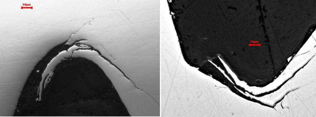
a) I look for the presence of corrosion products filling the first thread root past the fracture, and also within corrosion cavities of the fracture surface close to the outside. The distinctive iron sulphide, greigite, is absolutely diagnostic.
What we find is just clean, bare metal.
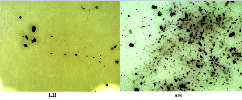
b) The SRB organism cannot thrive without leaving metal sulphides behind it. The Iodine-Azide test is a key diagnostic in this regard.
Both fracture surfaces recorded negative responses, making the active presence of the SRB organism very unlikely.
c) Normally, under the microscope, the signs of H embrittlement at the fracture are distinctive and are diagnostic of SRB attack. However, in our particular case, matters are not so straightforward.
All cases of SRB-SSC that I have examined have involved cold-worked 304 stainless steel with its substantial content of α’-martensite. This material provides for ready diffusion of atomic hydrogen, and consequently the possibility of catastrophic embrittlement over a wide area.
However, in our particular case we have measured the material as almost completely austenitic, and consequently hydrogen diffusion will be close to non-existent. Thus, no catastrophic hydrogen embrittlement would be expected. I believe this is why I have never verified SRB attack on a specimen of true 316.
Thus, we could reject the possibility of SRB-SSC simply on grounds that the steel is purely austenitic. However, there is no need to go out on that particular limb, given we have checks a) and b) as detailed above.
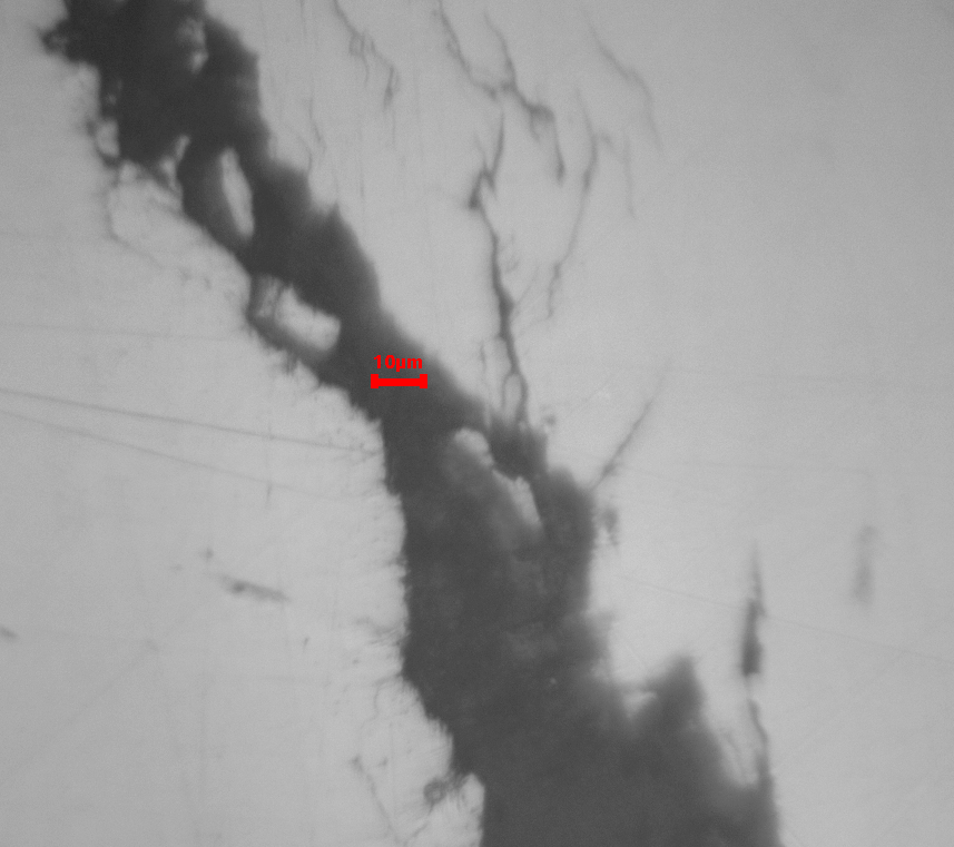
And just when we thought we had clarity, it becomes necessary to explain the morphology of those fine cracks I illustrated above. They point to a role for hydrogen in their propagation. In the photo below I have highlighted a number of such features.
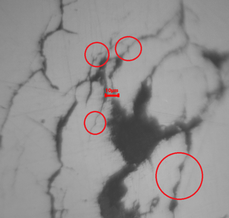
We have disposed of the possibility of hydrogen embrittlement via SRB attack, only to find evidence for hydrogen assisted cracking (HAC). I’ll develop on this finding in the next section. However, note for now that, because a fully austenitic steel is almost impervious to atomic hydrogen, what we see here is the result of hydrogen diffusion along a developing crack up to the tip to facilitate its advance. This is very different to what happens when hydrogen is free to diffuse through the metal, as is the case for cold-worked 304 under attack by SRB.
mode 3: Hydrogen assisted cracking (hac) sustained by An extreme cold-worked surface:
The hypothesis here is that severe cold work at thread roots creates conditions in which cathodic hydrogen‑assisted cracking becomes the dominant failure mechanism, rather than classic anodic slip‑dissolution SCC.
That sounds good, until you need to piece all the diverse literature together to justify it. I won’t attempt to do so here. This is a preliminary report.
Instead, let’s stay with that we can see. We’ve already shown the fine cracking we suspect to be HAC, so how about this extreme cold-worked surface at the thread root?
Today, good engineering practice preferences the cold rolling of threads rather than cutting them. And that is what we have here. Most old bolts I examine have cut threads, and to find rolled threads on these 24-year-old Petzl Goujons came as a surprise.
Cold-rolling, as a properly controlled process, leaves the thread root with a compressive residual stress. This is considered beneficial for SCC resistance. However, when incorrectly controlled, the very opposite of that which is desired, ensues. The material of the root and the thread flanks not only becomes extremely hardened, but a high residual tension is imparted. And this, even before we consider the impact of this treatment at the microstructural level.
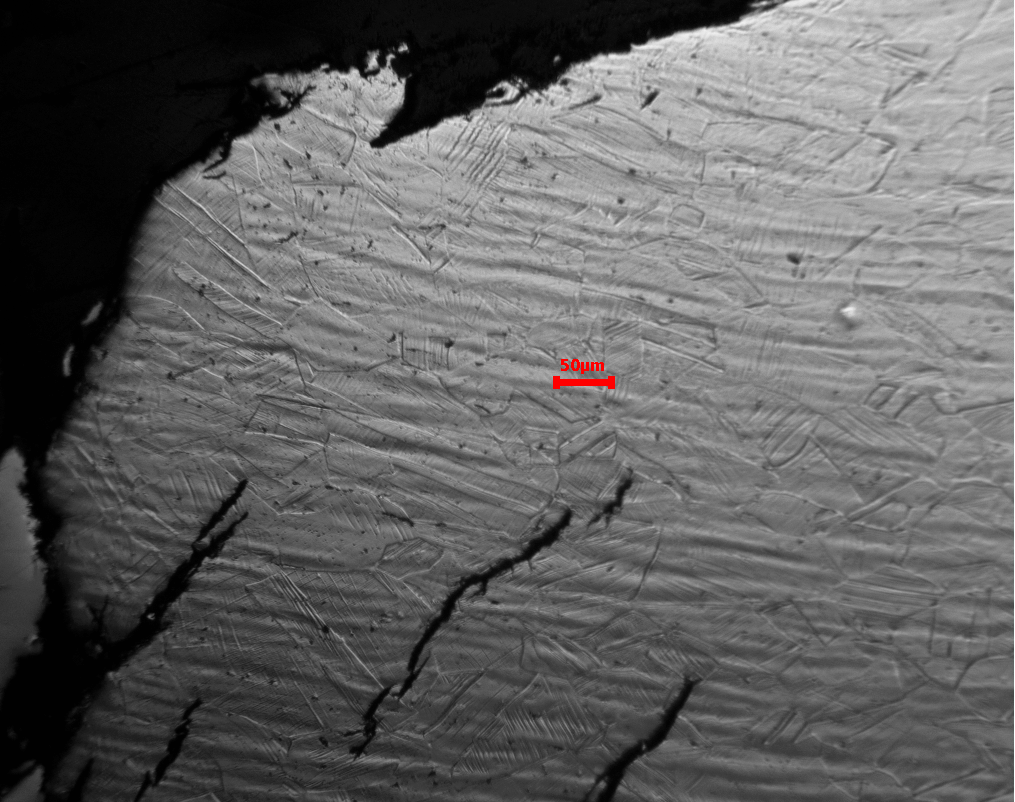
So, here we have a couple of thread roots from the LH anchor. The stress field tracks around the thread profile as would be expected.
LH anchor. Cracking under stresses imparted by thread rolling. Optical micrography of polished section.
And the RH anchor displays the same features.
Looking at what happens to the microstructure, it is clear all larger features are smeared and lost by the extreme strain.
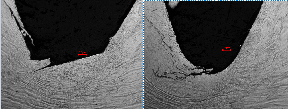
The same applies to the RH anchor.
Given the fact that the investigation is at a preliminary stage, I’m happy to accept this HAC mechanism as the most likely cause. I believe we have sufficient evidence to treat all Petzl Goujons with suspicion until they are proven innocent.
Conclusions:
Until proven otherwise, all installed 10mm Petzl Goujon expansion bolts of vintage, say 2000 to 2005, should be treated as dangerous. It should be emphasized that this condition arises from the nature of the bolt itself, and is independent of its installed environment.
Addendum:
17th June 2026
Bartek raises a good point in the comments.
He argues that this picture –

raises a problem for the central failure hypothesis. If this section of the bolt has not been cold-worked by thread-rolling, why do we see these stress cracks forming. Good question. I went and took some more photos.
Let’s look at the bolt again.
I would argue that the entire profile (ignore the clip) has been manufactured by cold rolling. Maybe in multiple passes, but plastic flow of metal from low to high points is how it got that shape.
The original micrograph was taken from an area roughly corresponding to the point A. You can see the start of the upsweep to the clip retainer on the left. Let’s take a closer look, but this time after the surface has been etched to reveal microstructure.
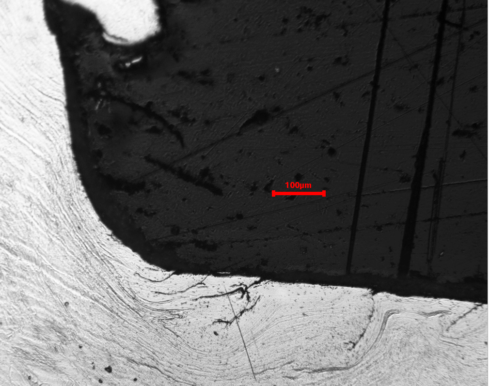
It is immediately clear that metal in this section has been every bit as aggressively cold-worked as the threaded sections we were looking at earlier. Ok, we might not have the stress-riser of the thread root, but clearly there are enough microstructural defects to initiate cracking in response to what looks like the same residual tension as we saw with the threads.
Evidence for extreme cold work extends right along the non-threaded section, exactly as you’d expect if it had been formed by cold rolling. The photo below is from the region marked B.
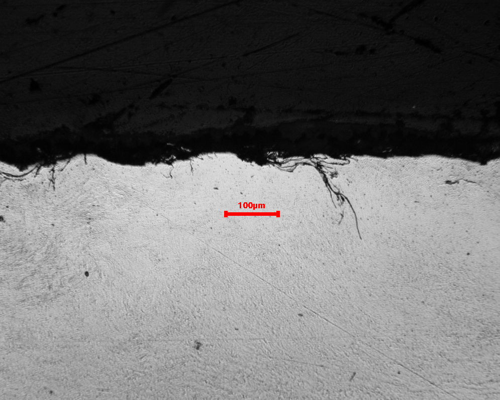
Notice the complete absence of the original microstructure, and the multitude of microcracks initiating from local deformities such a inclusions where they break the surface.
So, it is easy to see crack initiation occurring, even without the stress-riser of the thread root, but I wonder whether the conditions are right to propagate such cracks beyond the work-hardened zone. This seems to require conditions offered by the thread root. Maybe the lower oxygen potential, and/or lower pH is necessary?
Please read:
This sort of investigation is slow, technical, and expensive. The independent laboratory fee for chemical analysis of two St Savvas bolts alone was AUD $770, and further testing is expected. Crag Chemistry will continue to provide the time, scientific interpretation, technical reporting, and publication of findings free of charge, but we cannot keep personally absorbing the cost of every serious failed-hardware investigation.
If you value proper testing over rumour and speculation, please consider donating to the –
*Crag Chemistry Independent Bolt Failure Testing Fund*: https://gofund.me/1b3f3aed2.
The purpose is narrow and transparent: independent testing, interpretation, and public reporting of failed climbing bolts, anchors, and relevant rock environments, so that the whole climbing community can learn from these failures.
Discover more from Crag Chemistry
Subscribe to get the latest posts sent to your email.
35 replies on “Kalymnos – catastrophic anchor failure”
Thank you for your excellent work and publishing the report. Is there any indication of excessive torque applied during instalation, such as alongation of the threads near the fraction? Is the third broken bolt going to be analyzed?
We don’t have a lot of the threads showing to be able to judge this accurately. But looking at the pitch of the threads we have left, and looking at the diameter at the fracture point, I’d say not. Also, there is no obvious changes/distortion in the microstructure as we scan along the centerline to the actual fracture itself.
Yes, I have the third bolt and it will be analysed. In fact, Rebolt Kalymnos have collected a bunch of Petzl Goujons from other routes, and I’ll be looking at them also.
Thank you for your reply. Are you collaborating on this project with UIAA?
I know the guys at UIAA SafeCom and I keep them in the loop as regards what I’m doing and thinking. However, we are quite independent of one another, and they will do what they, as a group, think is appropriate.
Thanks for the post Dave. I was curious if you had got somehow involved I this case. I’m m glad that for know other 316L bolts are, in principle, safe.
Yeah, it’s funny, but every time I think “this is it, 316 has failed this time”, it manages to push the blame off elsewhere.
It real seems that it doesn’t fail, but…but… let’s wait a bit longer.
Hi!
I did my master thesis on some failures
In Italy back in 2013, great to see investigation is going on!
One curiosity: do you have a theory about the source of the H leading to HAC?
Hi Matteo, I remember seeing your paper. And yeah, I’m still working away at measuring stuff. Things are never as simple as they might first seem, and this one came as a real surprise to me.
You’re correct in that we need to postulate a hydrogen source. My understanding is that the excessive cold-working (tangled slip bands and the like) will give rise to an enhanced diffusivity for hydrogen at the thread root. This is important, given the almost non-existent diffusivity of pure austenite. So, if cathodic reactivity is going to introduce hydrogen anywhere, it will be at the thread roots.
Combine the above with the fact that this location is harbouring high levels of local stress, and you can see that crack initiation purely by hydrogen embrittlement might be possible.
However, we see no evidence of pitting anywhere, so the question arises as to where the anodic action is that provides the electrons for hydrogen generation at the thread roots?
More questions than answers, and I need to widen my literature search.
Thank you for a thorough investigation and interesting preliminary conclusions.
I came to learn from another climber that the Petzl Goujon bolts were made shorter (60mm) than regular bolts (70-80mm). This made them attractive for hand drilling bolts on big wall routes, since they were faster to hand drill. It also looks from the pictures published here that the bolts are quite short.
No idea if the short length would be related to different manufacturing process required, or to increased tensile stress/strain when applying torque to the nut. Only wanted to point out that these bolts seems to stand out from other bolts given their short length.
Yes, they are definitely 60mm. That is certainly short by today’s standards, but 25 years ago, maybe that was more acceptable? I’m trying to remember back that far but seem to remember 75mm was standard.
So the failure mechanism is essentially this:-
1) bolt is installed and torqued up to seat the sleeve. Bolt is in longitudinal tension.
2) time passes and stresses induced by the tension in the bolt cause cracks to start at the surface, most likely the areas in the depths of the threads where cold-rolling thread creation has already created stress
3) cracks propogate, aided by hydrogen-assisted cracking
4) bolt fails when load exceeds remaining tensile strength
It will be interesting to see the micrographs of the additional unbroken bolts. It’s also interesting that cracks are starting at the cold-rolled areas where the surface is compressed and thus has residual compressive stress – this is illogical, one would expect cracks to start where the surface is under tension.
Yes, and no. Because the rolling process has caused excessive deformation, the thread root was not in compression as would have been the intention but was put into tension. Not only that, because of the excess hardening, that tension could have been very high. This much we know because all thread roots showed multiple layers of cracking conformal with the thread root profile.
And for sure, I will be examining the unbroken bolts. My aim, going forward, is to see what light we can shine on the “bad batch” hypothesis.
Do you have examples of unused, ‘off the shelf’ bolts of the same type?
I am wondering how the cold-rolling process has produced tensile residual stresses at the thread roots rather than compressive ones. Have the threads been so badly formed and out of shape that this is could be the case? If so it should be evident by checking the dimensions of a new bolt or the part of the failed bolts outboard of the nuts.
I’m a retired engineer, not a metallurgist, but I have spent my working life specialising in stress analysis and fracture mechanics. I know how difficult it is to quantify the level of residual stresses in a component, although my experience is specifically related to welds.
This is why I’m puzzled to how the forming process has gone so wrong.
Thank you for your work.
Thanks for the interesting comment. We are guessing that these bolts were a special order, since there is no record of them in historical Petzl literature.
The fracturing at the thread root makes it clear that the residual stress must have been tension rather than compression.
I need to do a heap more reading on the subject, and may have to pay for –
N. M. Ferguson & J. M. Barsom (ASTM STP 1236, 1995)
“Residual Stresses in Threaded Fasteners.”
If you look at the flowlines in the micrographs, what is happening is certainly a lot more than simply straining the outer layer. Some explanations I’ve read say it occurs because the inner material ends up with higher strain than the outer, and thus when pressure is released, the residual stresses are tensional.
Certainly, if I look at say a THE 316 bolt, the depth of penetration is less, and the flow lines are very orderly.
In any event, I’ll be examining many more bolts of this type, both fractured and unfractured. After that, the picture may get a bit clearer.
As I previously said I’m not a metallurgist and I’m not that familiar with micrographs. I’m a retired mechanical engineer who specialised in stress analysis and did some fracture mechanics, the latter being a bit of a cross over into metallurgy.
In fracture and fatigue we always consider tensile stress normal to a crack, tending to open. I assume it is always tensile stress normal to a crack that is the cause of the type of crack propagation that you are investigating. This stress could be residual from the forming process, due to bolt preload and due to the climber’s weight. In non stress relieved welds we assume a residual tensile stress equal to the material yield stress (or equivalent for stainless). I guess you could have the same level of residual stress from the forming process i.e. yield (or 0.2% proof stress for stainless).
I’m sure the distribution of residual stress and plastic strain will be complex. I’m also not familiar with thread rolling but as plastic deformation is at constant volume I imagine that something like 9-9.5mm diameter bar is used to roll a M10 thread. As the thread roots are pushed in material must flow outwards to form the crests. I think the hoop and radial strains will be compressive at the root and tensile at the crest. I’m not so sure applying my logic to the axial direction, but based on the accepted notion that rolling is beneficial for fatigue, I guess the strain must be compressive at the root. Then there is the problem that a tensile strain does not necessarily correlate directly with a tensile stress due to the constraint of adjacent material and Poisson’s ratio. After all this waffle what I’m coming to is that a non-linear finite element analysis (NLFEA) may be the best way to understand what’s going on. Analysis software such as Abaqus Explicit could be used to model the thread rolling process. This software allows ‘adaptive meshing’ which is necessary where you have large plastic deformations like here. As deformation develops the initially regular shaped finite elements would normally distort so much that the results become inaccurate. Adaptive meshing automatically re-meshes so that the results stay good. I would start in a simple way with an axisymmetric model of a normalised stainless bar. The thread roll would be modelled as rigid surface like a thread chaser. This would be pushed into the bar to form the thread. Initially I would assume no contact friction (or very low). Of course the reference you quoted may have already done such an analysis!
Trying to fathom out how I would develop this simple analysis to more accurately simulate the rolling process made be look back at some of your micrographs of the thread root. I guess the thread rolls should ideally be hard, smooth and well lubricated. The micrographs show fine slivers stripped away at the root. Could these have been caused by the rolls ‘picking up’ the surface of the stainless steel due to rough rolls or lack of lubrication? If they were caused by the forming process they may well be visible in the threads outboard of the nut where the bolt hasn’t experienced preload or climber loads.
You mentioned that the ‘flowlines’ (I think) shown in the micrographs imply tensile stress and I was wondering why this is. The yield and plastic flow rules I’ve used (Tresca and von-Mises) are based on shear and you would get the same shear stress in a simple bar whether under axial tension or compression. Therefore, my question is how do you know the flowlines are due to tensile and not compressive stress.
My final point is about what testing is done by bolt manufacturers. Do they or could they do impact tests (like a Charpy test) on a number of bolts out of each batch?
This comment is in response to the last long post of yours. For some reason WordPress doesn’t give me the possibility of replying in line.
Thanks for sharing your thoughts on this. I agree that it becomes challenging once you think about it.
Re. flow lines: The reality is that what we are looking at differences in the electrochemical properties dispersed across the cross section. If you don’t do the electrochemical etch (the sample is the anode) then you see nothing. So, this form of micrography is a great storyteller and we need to be cautious in our interpretations.
For certain we know that metal is displaced by plastic flow from thread root to thread crest. The local strains can be substantial, and even for a 10% nickel austenitic steel, there are going to be plenty of slip-band pileup and microstructural rearrangement. This will show as electrochemical differences, and in the pattern of such, we can imagine we are looking at the direction and destination of plastic flow.
Note that the etch is done at 3V. If I had chosen, say 6V, I would see a quite different emphasis applied to microstructural features.
I need to do some reading. I’m very sure this subject is well studied, and if you brought some serious SEM technology to bear, then we could be a lot more exacting in describing what is happening there.
Do you think that in this case if 20 years after bolt placement someone with good intentions came and tightened up the bolts, it could make things worse? Related question: how important is proper torque?
Looking at just the two anchor bolts, there is no evidence of over-torquing. There is no reduction in diameter or extension of the thread pitch. Also, the microstructure is consistently the same right up to and including the fracture edge.
In my opinion, climbing bolts are rarely torqued-up precisely, if for no other reason, unlubricated stainless steel is prone to galling. As long as there is sufficient outward force on the sleeve to grip the rock, then, a bit like a cam placement, the harder you pull, the harder it hangs on.
Reduced ductility from the cold rolling process a potential factor once installed and under tension?
In an ideal world, the reduction in ductility would extend no more than 100um of so into the bolt, so the toughness should not be greatly affected. However, as a general consideration, I do worry that lack of QC means over-hard bolts make it into service. We overvalue tests of ultimate breaking strength, whereas we should be looking at the area under the stress-strain curve.
Thank you.
My2cents is that brand very likely did not produce those bolts. So… there might be much more pieces made with those press machines, that we do not know how to spot on. I suggest to contact SPIT (Société de Prospection et d’Inventions Techniques) now ITW.
For sure. I responded to your FB post that I too suspect these Petzl bolts are an OEM from Spit. I’d be very interested to see any documentary evidence for this.
As you say, the reasons for understanding the manufacturer are substantial. What other dangerous bolts can be out there?
Watch this space! I’ll soon be reporting on an almost identical Spit Fix bolt that seems to have failed by exactly the same mechanism.
Thank you, David, for your insightful analysis. Fortunately, in Poland, since the boom in fixed anchors began, we’ve been using chemical anchors. However, given the material flaws in steel, even they aren’t entirely safe. I’m a metallurgist (steel forming) and geologist, and in Poland, I train crews and conduct non-destructive testing of anchors. Best regards,
Wlodek Porebski
Yes, even glue-ins can suffer problems with poor steel. From an engineering point of view, 10mm bolts are underspecified for the potential load they may have to carry. Proof of this is you cannot fully verify the capacity of a 10mm bolt without taking it well into yield and thereby destroying it.
Hello, thanks for this great work.
Did you eventually perform hardness tests to compare these bolts to other more current 316L bolts? Cold working level wouldn’t be related to hardness?
Applying high strength level in tightening the nut with a not dynamometric wrench could affect an already cold working stressed structure?
Thank you in advance
I’d love to do a full engineering stress-strain plot, but that’s not possible with fragments. I had a quick look at hardness using my Leeb tester, but I don’t trust it when working with a small sample. I’m looking into getting a profile done with a micro-indenter, but I think I’ll first wait till I have more samples and see where that takes us.
Thanks for the analysis! Sent some € for funding your expenses.
What I don’t get, if I just apply logic… the route surely had a crux, where most falls should have happened, which would have introduced a higher force to that single bolt.
If we apply that bad batch/manufacturing issue to the crux bolt, that should have broken much earlier than the belay bolts that usually get a much lower static force. Or are the force vectors important and the overhang and repeated swinging over 24yrs did increase the fissures and finally the failure.
Thanks for the donation.
That’s an interesting argument. So, the two bolts that happened to be the anchor bolts failed together before the crux bolt. I get the logic, but it implies a very consistent weakening process, and one that applies uniformly across all bolts.
On that route, during the process of rebolting, all remaining bolts got a whack with a hammer. Some snapped some did not. The obvious conclusion is that the rate of degradation is not uniform across all bolts on the route. However, I’m assuming nothing until I have analysed them all.
The bad batch theory depends upon finding evidence that all bolts, both failed and not, exhibit exactly the same composition (ie same melt) and are excessively thread rolled to the same degree.
This will take some time, and thanks to the inflow of donations, will most certainly get done.
Hello,
I apologize for what may be a silly question, but after reading your very detailed report (thank you for that), I didn’t understand who commissioned you to produce it or which laboratory conducted the tests you describe.
Hi Oliver,
Nobody commissioned me to produce the report. This is true of all posts on my website. Apart from initial support from UIAA to setup my lab, I personally fund the entire enterprise. This is the first report where I have gone outside my own laboratory to get analysis done. Given the serious consequences of the failure, I felt obliged to seek OES analysis of the bolts to rule out the possibility of anything funky going on. This is expensive and is the reason I have set up a GoFundMe account.
How does the cracking from unthreaded (non cold worked supposedly) bolt section support the root cause presented in the article?
That’s a very good question.
I’ve added an addendum to the main post with some new micrographs that addresses your point.
Long story short, I believe the evidence is that this section is every bit as cold worked as the threaded section.
Thank you sir!
Flow lines on the shank section looks absolutely terrible with essentially nonexistent at cracks origins. That possibly indicates a kind of a rollover / lapping. I wonder if there are any signs of crack propagation in these (as well as some of the root ones).
Hi David. My observations are that the roots of the threads show laps from the cold forming process not a crack as such. At least initially. The lap as you would expect is a fine initiator for the damage mechanism you propose which explains the cracking over the years and eventual failure. I have seem similar root laps leading to failure in L7/B7 studs. Those examples arose from inadequate heat treatment leading to single digit CVN values. I am in Perth and use similar labs to you for your failure analysis.
Also I may have some unused Petzl bolts from that era. Let me check….regardless worth looking at a few examples of expansion bolts and industrial fasteners to see what the exhibit relative to this example.
Given there’s 1000s installed for rock climbing of these bolts also with rolled threads…. Surprising there are only these two failures ? I am wondering if there is an environmental contributor that made these Kalymnos ones susceptible.
Hi Neil, thanks very much for the comments.
So we might be looking at successive laps in the thread-rolling process? Now there’s a thought for sure. In any event, it all points the one way, and that is poor control of the rolling process is setting up for catastrophic failure decades down the line.
Right now, I’m looking to get more information on what is happening at those thread roots. SEM with EBSD would be nice. Let’s see what we can do.
Also, as you suggest, why out of the thousands possible, just these failures? Such thoughts have us sampling this bolt type, not only on Kalymnos but elsewhere as well. The amount of work involved in pulling all this together is huge, but I feel it is vital to get a handle on what is happening here. Measure more, speculate less has to be the way to go.
It may be that we’ll get lucky and can show just one batch of Petzl Goujons was poorly manufactured, but as a caution against optimistic thinking, I can reveal we are 100% certain that these bolts were manufactured by SPIT, and the identical SPIT FIX is a very common bolt across European crags. Immediately prior to the Kalymnos accident I was working on a SPIT FIX bolt from Sesimbra in Portugal that had failed in exactly the same manner. I’ll eventually write this up, but for now, it flags a warning that things might get quite involved.